The Architectural Institute of Japan (AIJ) has presented a number of well-known benchmark scenarios of wind simulation.
The following article deals with "Case E - Building Complex in Actual Urban Area with Dense Concentration of Low-Rise Buildings in Niigata City".
In the following, the described scenario is simulated in RWIND& 2 and the results are compared with the simulated and experimental results by AIJ.
Das Architectural Institute of Japan (AIJ) hat eine Reihe an bekannten Benchmark-Szenarien für Windsimulation vorgestellt.
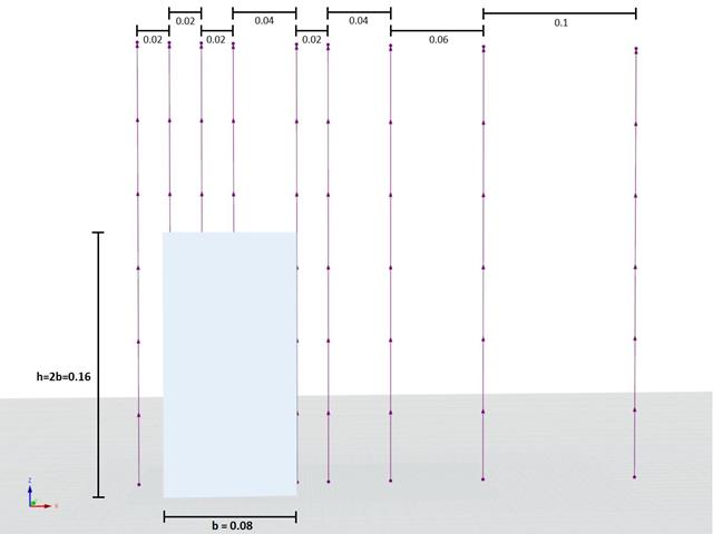
Der Nachfolgende Beitrag dreht sich dabei um den "Case A - high-rise building with a 2:1:1 shape".
Im Folgenden wird das beschriebene Szenario in RWIND2 nachgebildet und die Ergebnisse mit den simulierten und der experimentellen Resultate des AIJ verglichen.
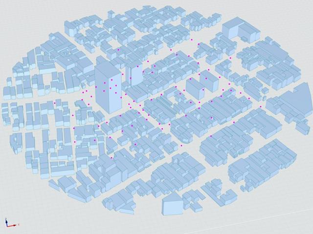
The Architectural Institute of Japan (AIJ) has presented a number of well-known benchmark scenarios of wind simulation.
The following article deals with "Case D - High-Rise Building Among City Blocks".
In the following, the described scenario is simulated in RWIND 2 and the results are compared with the simulated and experimental results by the AIJ.
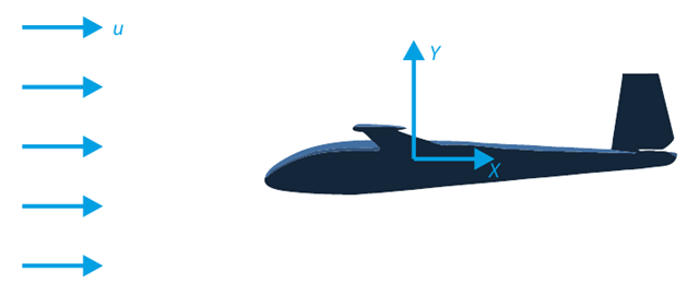
The goal of this verification example is to analyze the fluid flow around the glider. The task is to determine the drag coefficient and the lift coefficient with respect to the angle of attack. These coefficients can also be drawn into the graph of the drag polar. The limit angle for laminar fluid flow around the wing profile can also be determined from the velocity field. The available 3D CAD model (STL file) is used in RWIND 2.
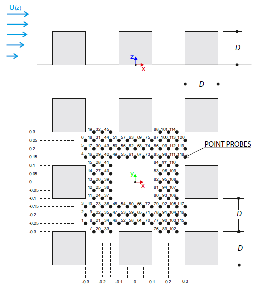
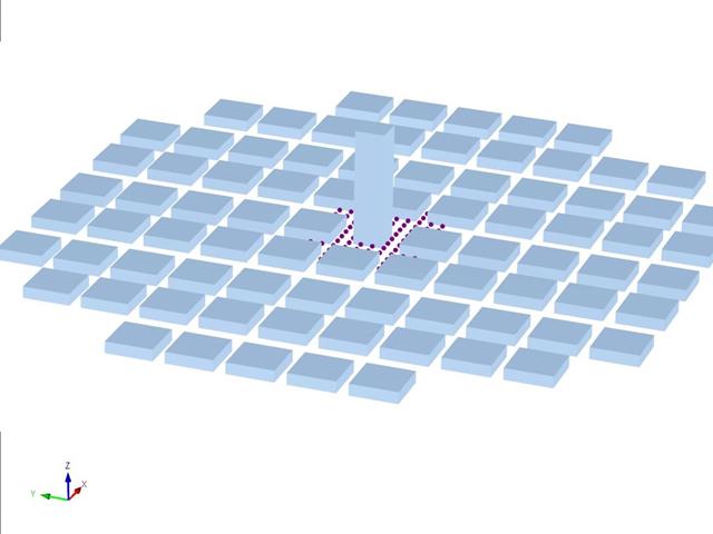
The verification example describes wind loads in several wind directions on a model of a group of buildings. The model consists of eight cubes. The velocity fields obtained by the RWIND simulation are compared with the measured values from the experiment. The experimental data are measured using a thermistor anemometer in the wind tunnel.
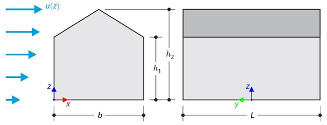
This verification example compares wind load calculations on a duopitch roof building using the ASCE 7-16 standard and using CFD simulation in RWIND Simulation. The building is defined according to the sketch and the inflow velocity profile taken from the ASCE 7-16 standard.

This verification example compares wind load calculations on a flat roof building using the ASCE 7-16 standard and using CFD simulation in RWIND Simulation. The building is defined according to the sketch and the inflow velocity profile taken from the ASCE 7-16 standard.
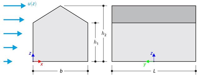
The verification example compares wind load calculation on a building with a duopitch roof using the standard EN 1991-1-4 and using CFD simulation in RWIND Simulation. The building is defined according to the sketch, and the inflow velocity profile is taken according to the standard EN 1991-1-4.
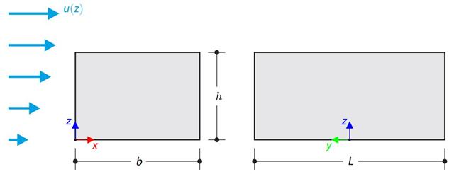
The verification example compares wind load calculation on a building with a flat roof using the standard EN 1991-1-4 and using CFD simulation in RWIND Simulation. The building is defined according to the sketch, and the inflow velocity profile is taken according to the standard EN 1991-1-4.